Thank you for your interest in our motorized crossing gates!
We have been working on the design of our crossing gate system for several years. One of our primary goals was to keep it simple to install and operate. The gate movements also had to be smooth and dependable and the gates had to be nice looking even at n scale. We introduced the G Scale version first because that gave us a chance to work all the operating factors at a larger scale. The components are made with a combination of aluminum and 3D printed parts. There is a lot of manual labor involved in making the gates. The rod has to be cut and a hole “carved” for the LED wires. Many painting steps are involved along with an embossing step for the lettering and all the 3D printed parts have to be processed. This gives you a only a small glimpse into what’s involved.
Below you will find videos of our product announcement of each of the scales. You may also find over 125 videos on our YouTube Channel that demonstrate all our different product offering’s. If you have any questions please email or call us. Support@ModelTrainTechnology.com. 407-242-5436.
Jim
Founder
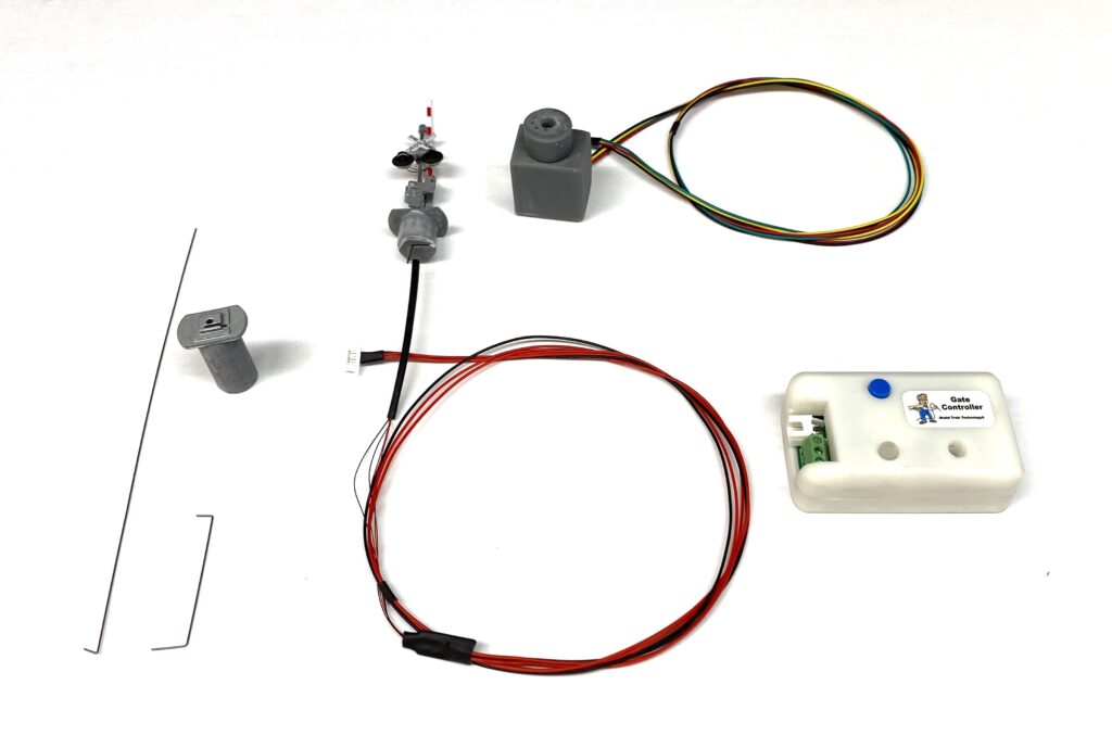
Our motorized crossing gates have only three components: The gate, the gate controller and the motor. Once you drill the 1/2″ hole, the rest is easy.
HO Crossing Gate:
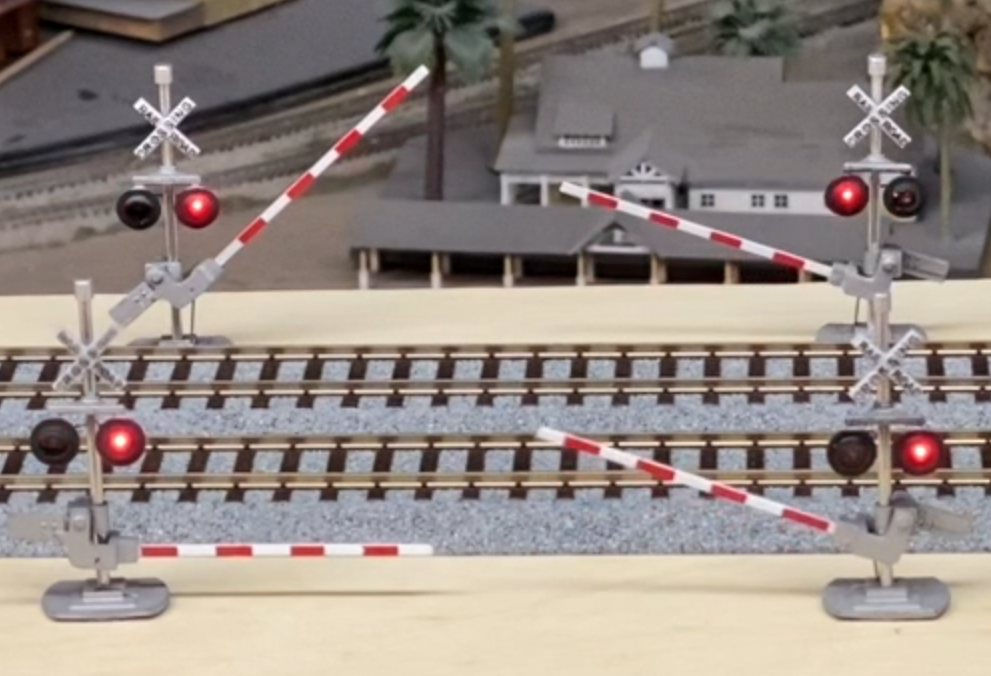
Shown above is the demo model of our HO Scale Motorized Crossing Gate. We show four gates facing forward so that you can see what’s going on in the video. You can order Left-hand and Right-hand facing gates.
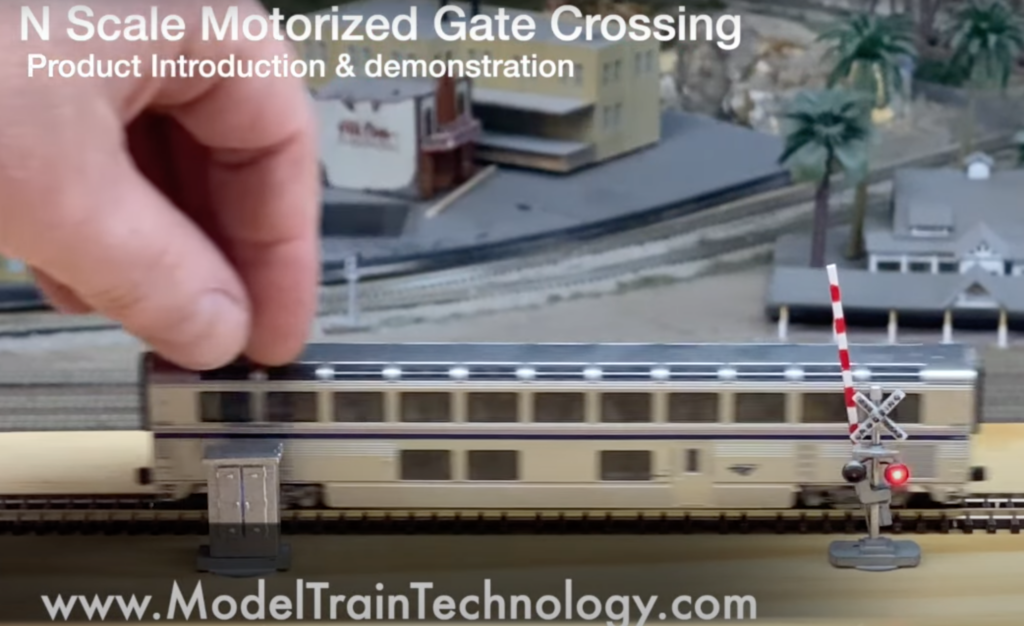
Shown above a single gate crossing for N Scale.
KIT & PACKAGE items description
Here are the components of a single crossing gate. Each gate requires its own motor and controller. You will notice that there is what we call a “plug” at the base of the gate. This fits into the 1/2″ hole and secures both the gate and the control wire. Plugs are available for different size layout base thickness (1/4, 1/2 and 3/4″). If your layout is thicker than that or the distance from the gate to the motor will be longer than 2″, you can use the extension wire (included) and make up your own control wire. This works well up to about 4-5″ with any further modification. The motor is attached to the underside of the layout surface via a magnet. We provide several self-stick magnet “plates”. See the videos for more information on this.
FAQ
Q: What power supply is needed?
All our products run on 12VDC.
Q: How do you trigger the crossing gates?
There are three methods to triggering the gates. The most typical one will be though the use of one or more MTT Precision Detectors. Second, you may use a toggle switch. Third, all Gate Controllers come with a DCC Accessory receiver. Simply assign the Controller a switch address and use Thrown/Closed to activate the gates.
Q: Can I install the gate if my layout is thicker than 1″?
Yes, the plug will only need to be 3/4″ and we provide a longer actuator wire so the motor can be a far as 4″ down from the gate. The extra wires in included with all kits.
Q: Can multiple gates be trigger with one sensor?
Yes, by connecting the sensor (Precision Detector) wire to all the DETECT terminals on the controllers, they will all be activated by one or more sensors. On each Controller you can set the delay to none, 5 seconds or 10 seconds.
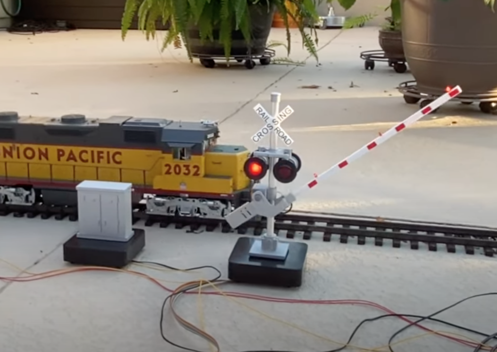
Q: How do I get a G Scale gate to face the right way?
The G Scale Crossing are all four-light version. Therefore, you only need to turn the cross buck around to get it facing the right way.
Q: How do I make the gates move synchronized up and down?
Each gate (via the Controller) has three trigger options options: 1) move when the light go on, 2)wait 5 seconds after the lights go on, 3) wait 10 seconds after the lights go on.
Documentation
All product Documentation is available under the “TECHINCAL” tab. Click here.