(Items in BLUE are Videos, items in RED are Documents
SPEED STICK
Speed Stick v5 Bluetooth Manual
Speed Stick Manual v4.1
Speed Stick Manual 1.4a
Speed Stick Troubleshooting
Speed Stick HOW-TO Video
Speed Stick jmri MANUAL
Speed Stick jmri SCRIPTS (Download)
LED Lighting Controller 5 – MAIN UNIT:
Product Announcement Video
Quick Start Video
LLC-5 MAIN UNIT Operating Manual. v1.1b
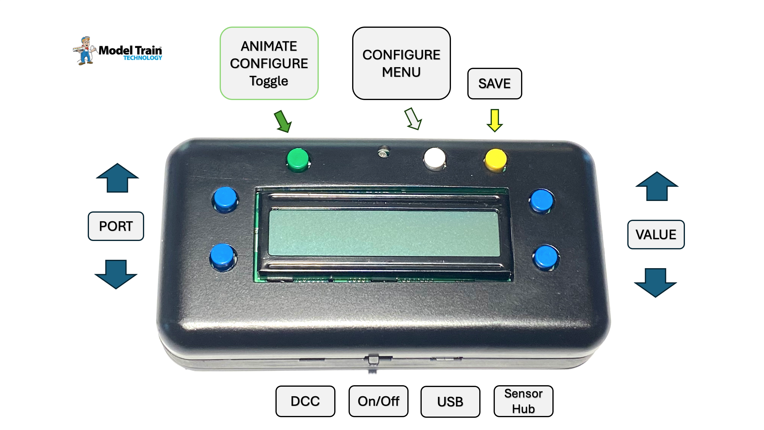
KEYPAD BUTTON Diagram
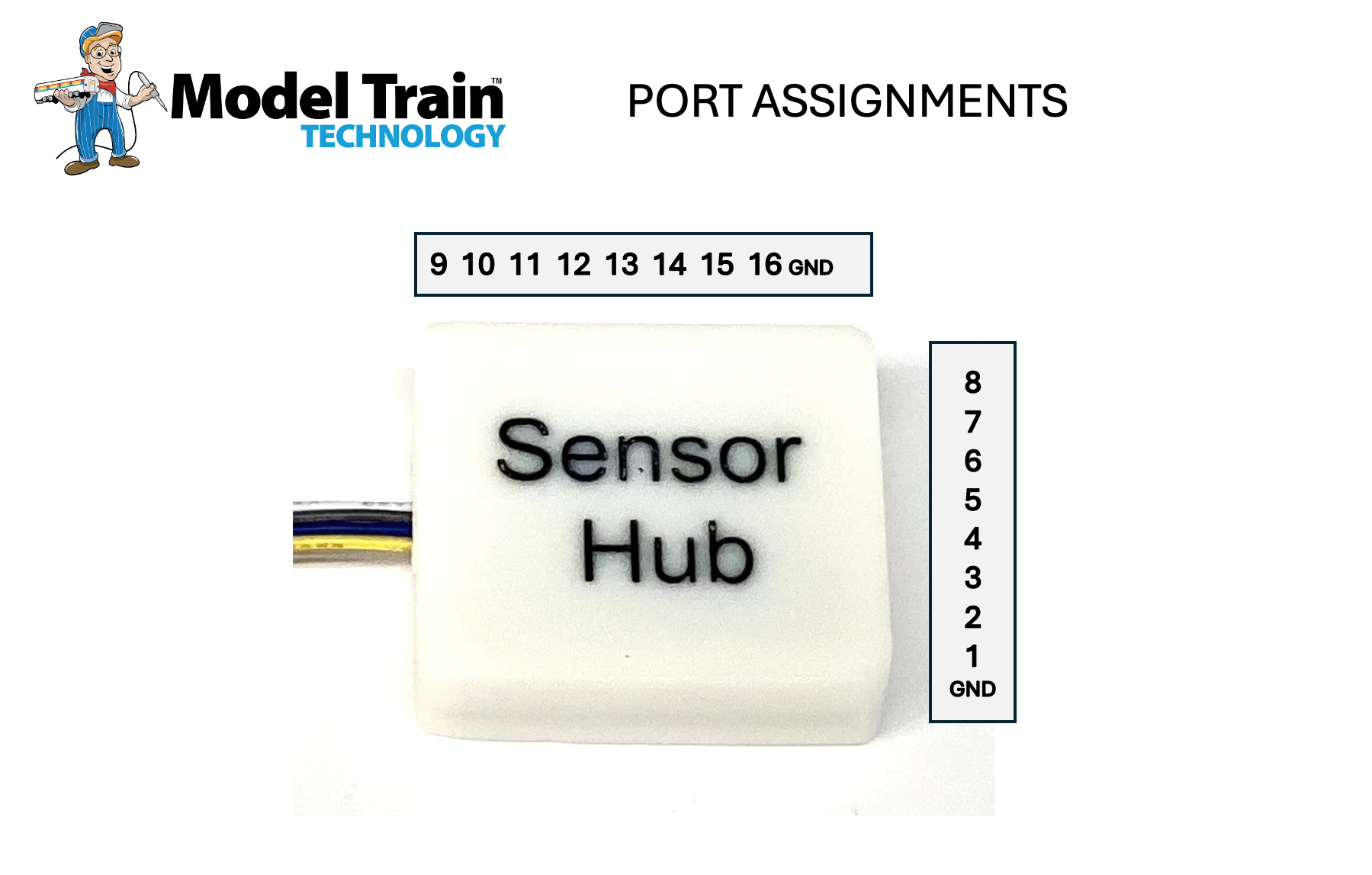
SENSOR HUB Port Assignments
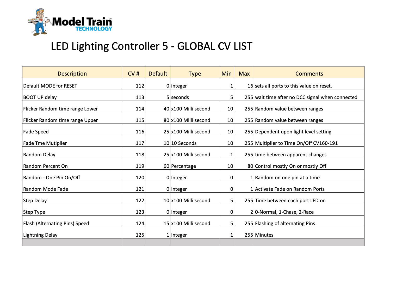
GLOBAL Configuration Variables (CV) prior to version 3.0
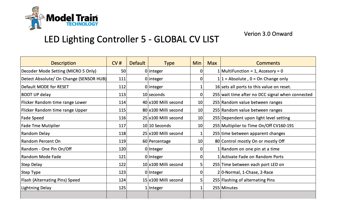
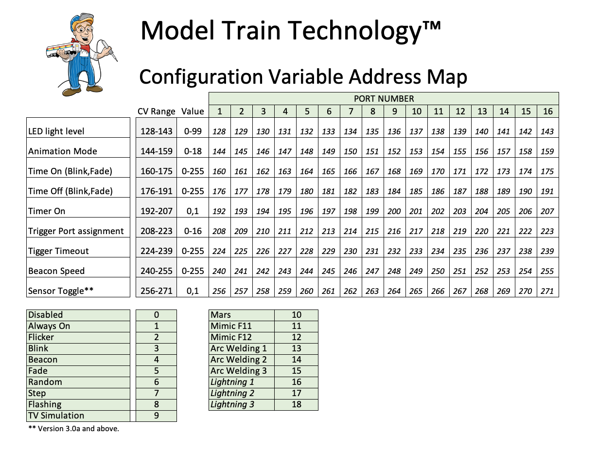
GLOBAL Configuration Variables (CV) – Version 3.0 and later
PORT Specific Configuration Variables (CV) Map
VIDEOS:
Quick Start Introduction
Setting up the TV Simulation
Adjusting the BLINK function
Troubleshooting: TEST Mode – are the lights working?
How to safely remove the LED Test board and Terminal Block board
Resetting the Controller
Setting the DCC Address
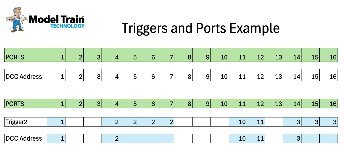
Using Triggers via DCC to turn ports on and off
Triggers and Ports Example 1
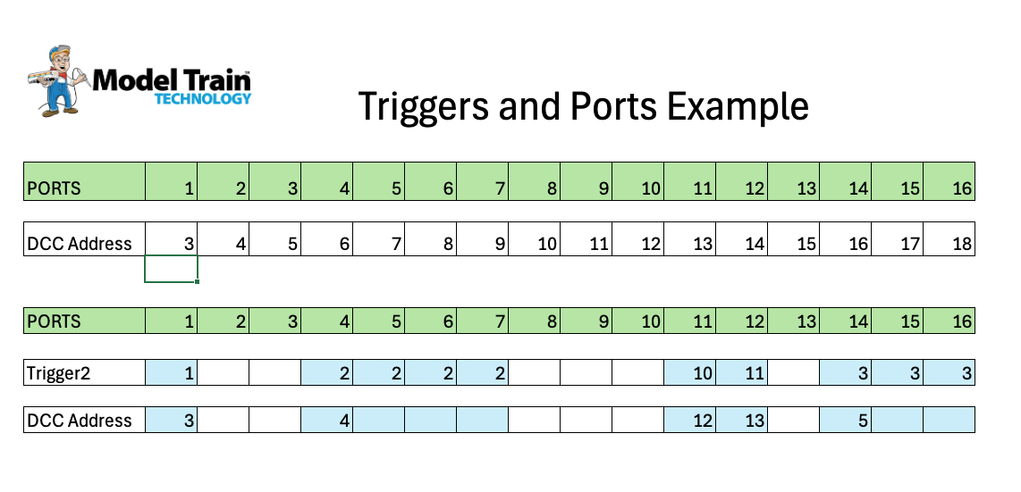
Triggers and Ports Example 2
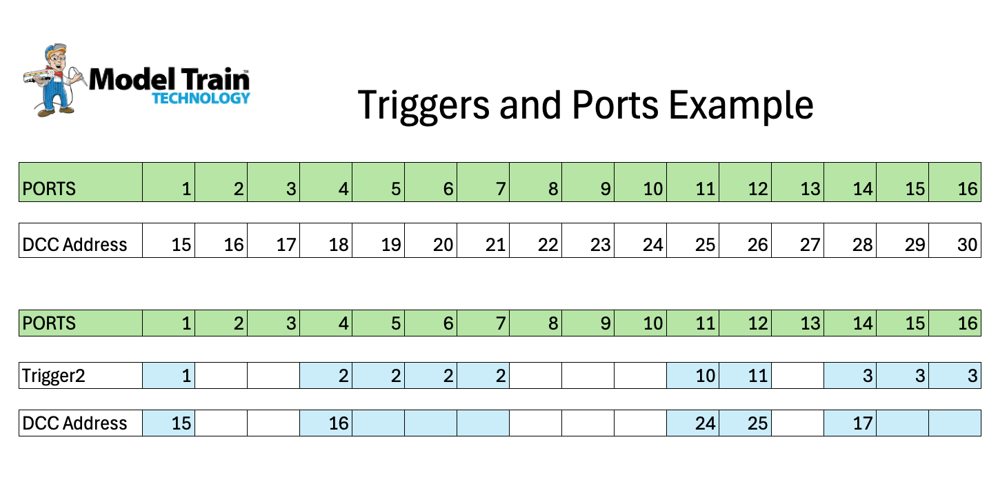
Triggers and Ports Example 3
LED Lighting Controller 5 -MICRO board:
LLC-5 MICRO Operating Manual 1.1a
VIDEOS:
Using the USB Cable to Configure the MICRO-5 without DCC
Basic Configuration and setup for use with DCC
Setting up Triggers with DCC and the Configuration Table
Configuring the Sensor Hub to work with Triggers
Configuration Animation via DCC Programming Track
Basic Animations with DCC Multifunction Mode
LED Lighting Controller 5 SENSOR HUB
Configuring the Sensor Hub to work with Triggers
All Other Products:
DC Only Passenger Car Light Board INTRODUCTION and SETUP VIDEO
DC Only Passenger Car Light Board Manual
DC Only Caboose Board (N/HO)
TRAIN SENSE INTRO VIDEO AND INSTRUCTIONS
Train Sense Passenger Car Light Boards (N & HO)
Train Sense Caboose Boards (N & HO)
Yankee Flyer Lighting Kit Manual 1.8a
Standard Passenger Car N/HO LED Light Board Manual
Signal Controller (LED & FIBER)
Signal Controller (Searchlight)
Dwarf Signal Controller Manual
Dwarf Signals for LED Setup Video
Precision Detector (Side of track and MilesPost)
Precision Detector (N Scale installation)
Precision Detector (NANO) though hole and slide under
Precision Detector (NANO Dual) Direction Sensing
Motorized Gate Controller (N & HO Scale)
Motorized Gate Controller (N & HO Scale) SERIES 3 MANUAL
Motorized Gate Controller ( N & HO Scale) SERIES 3 VIDEO
Railroad Flasher – Configuring the Signal Controller Video
Bell Module Manual
Bell Module Setup Video
Sound Module
SMART Switch
SMART Relay
Standard DPDT Relay
DCC DPDT Relay Controller
Coil Detector
CTC Panel Hookup
G SCALE
G Scale Universal Signal Controller
Precision Detector MAX (G Scale)
Motorized Gate Controller (G Scale)
Installing Feet in the Rubber Block
Wiring Diagrams:
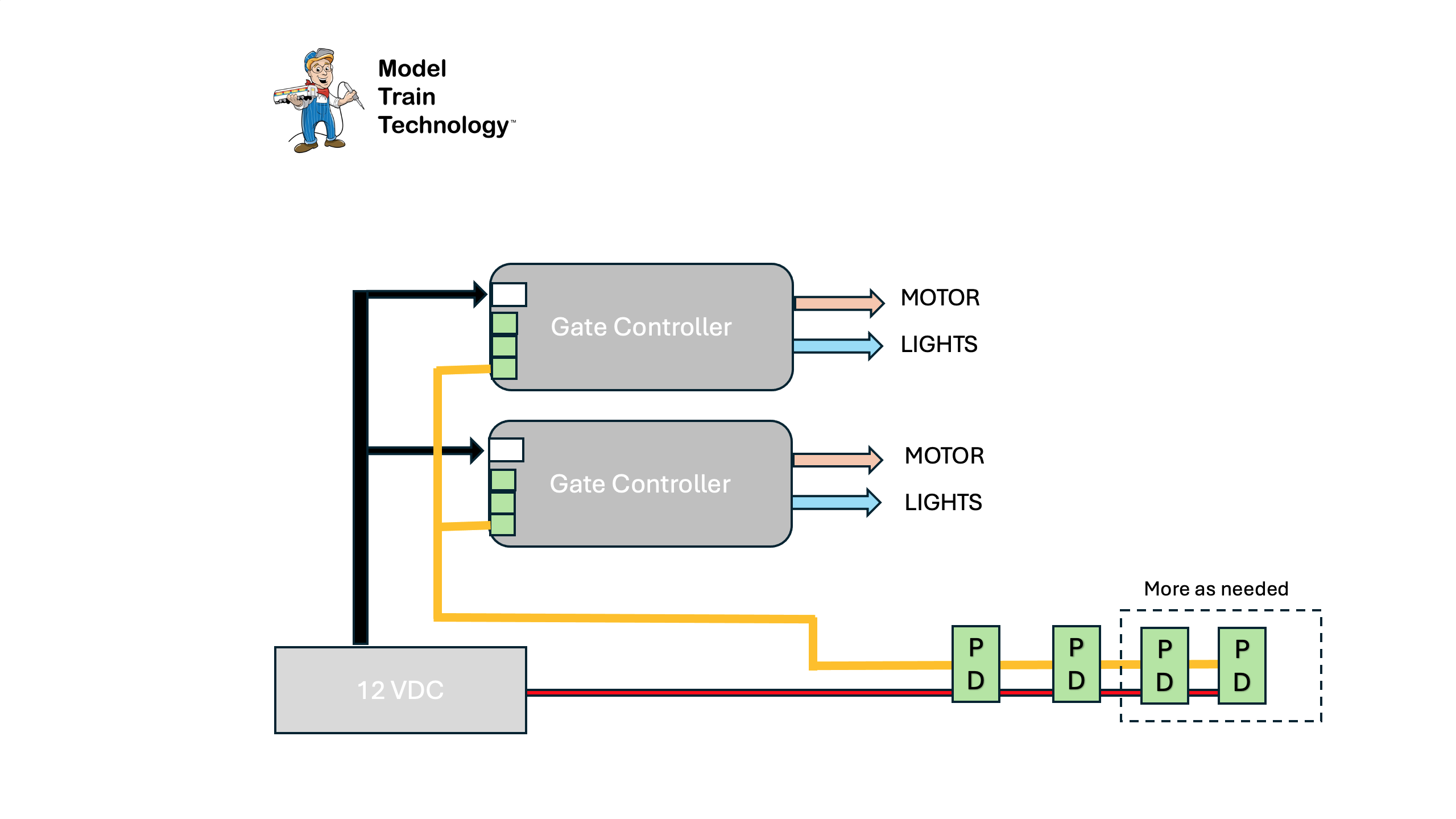
Motorized Gate Crossing wiring diagram
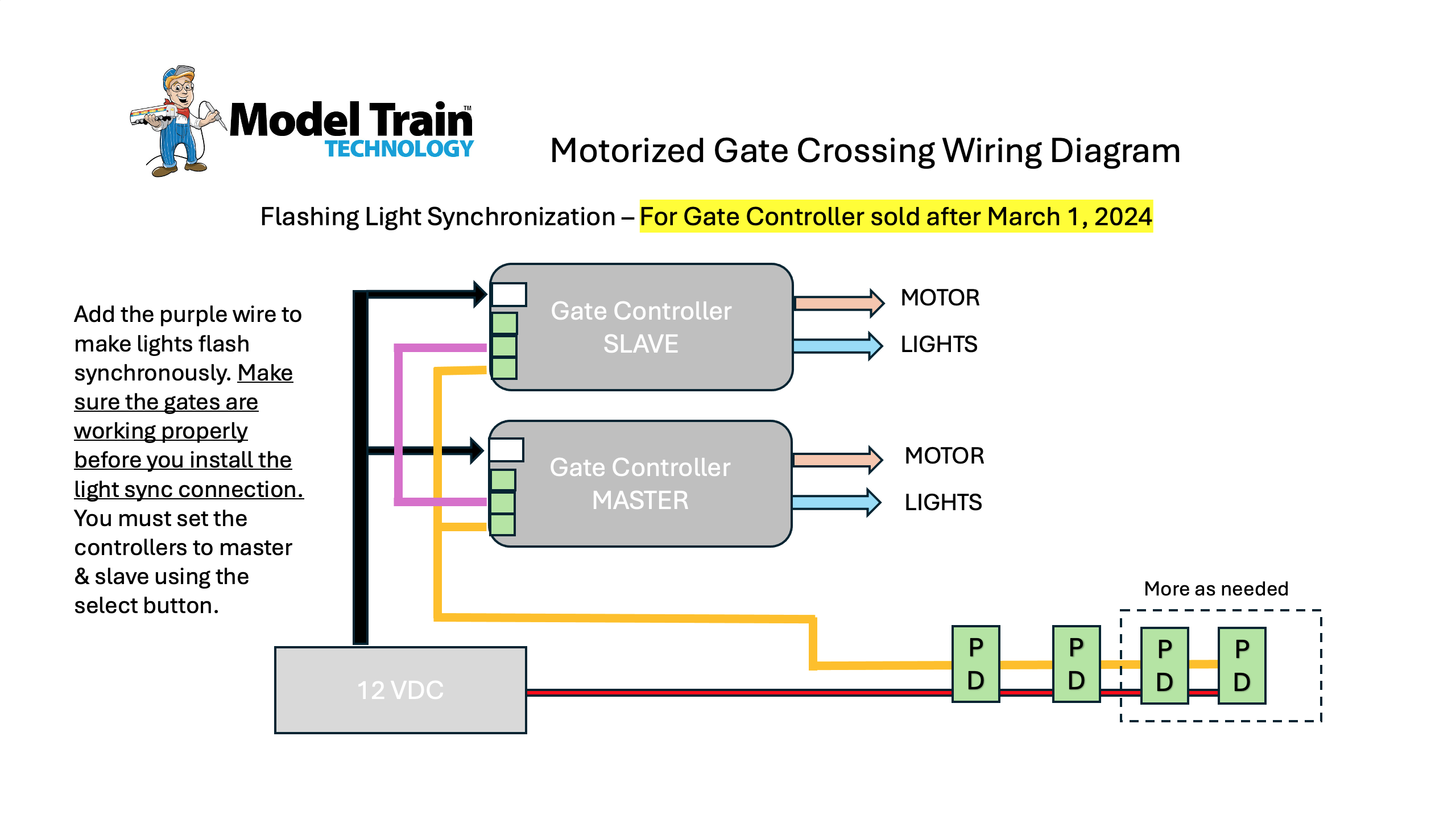
Flasher Light Synchronization diagram
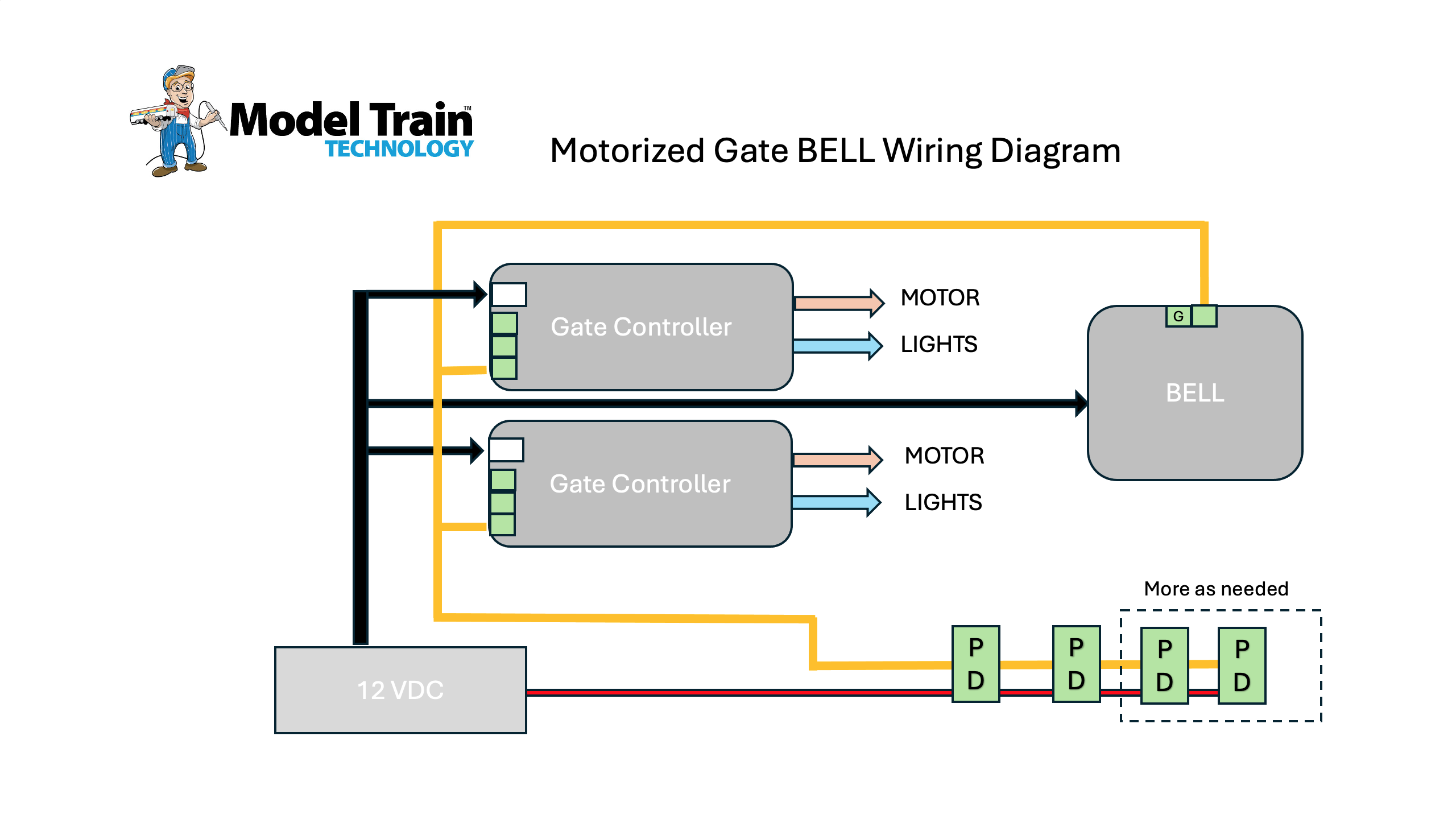
Motorized Gate BELL wiring diagram
Railroad Crossing in a box
Protect your Turnouts
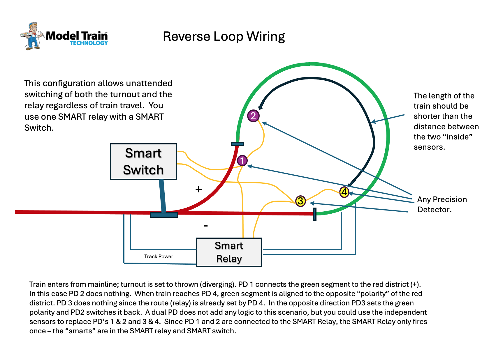
Reverse Loop wiring with SMART Relay and SMART Switch
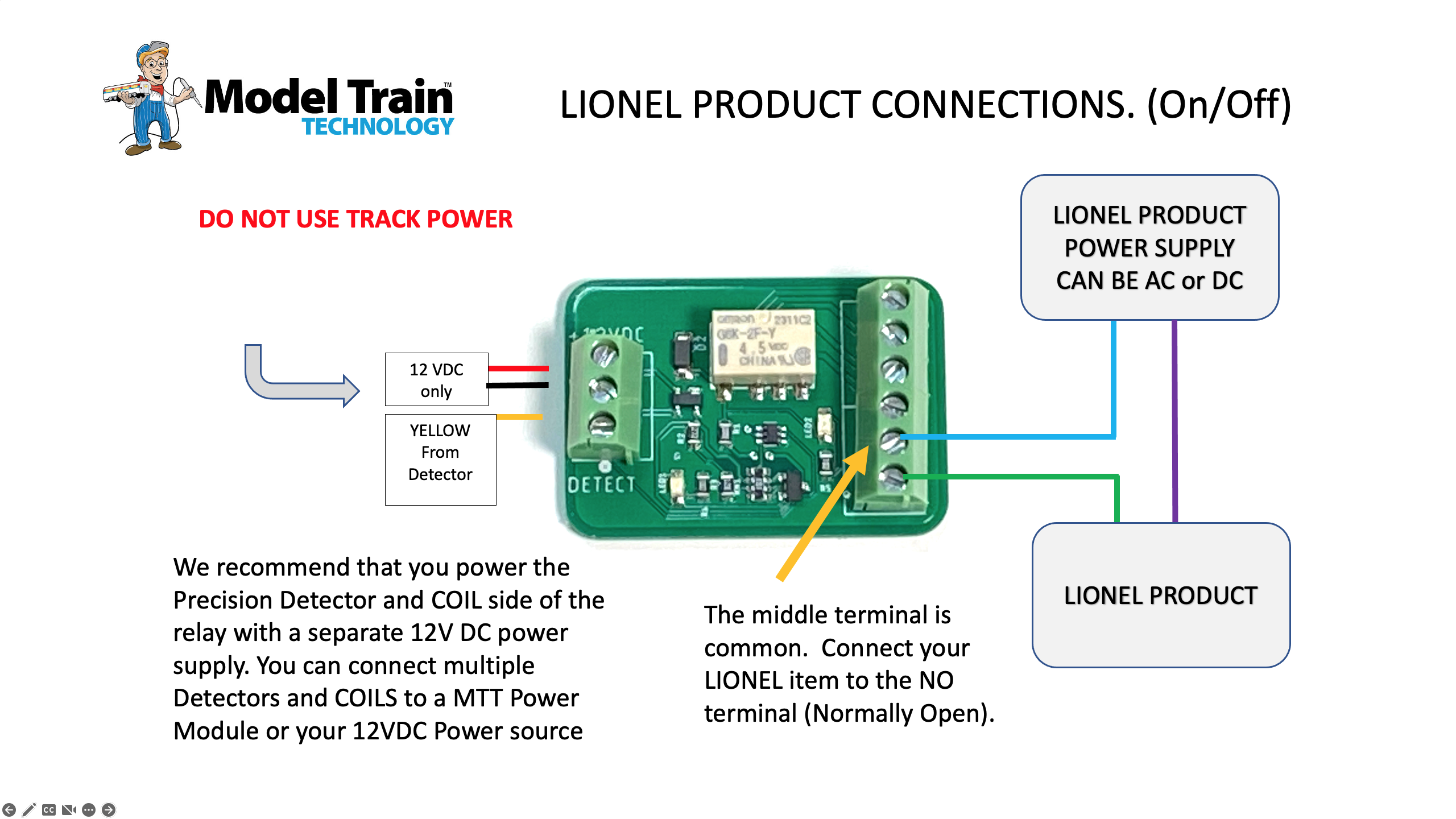
Basic Lionel Wiring for Sensor and Relay
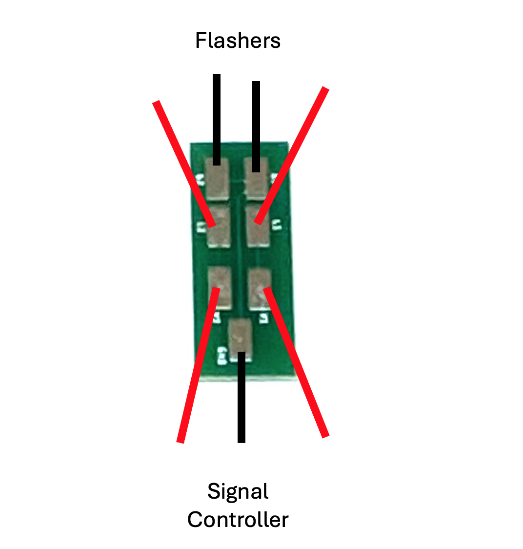
Flasher & Gate Solder Pad Wiring Diagram
(Items in BLUE are Videos, items in RED are Documents
SPEED STICK
Speed Stick v5 Bluetooth Manual
Speed Stick Manual v4.1
Speed Stick Manual 1.4a
Speed Stick Troubleshooting
Speed Stick HOW-TO Video
Speed Stick jmri MANUAL
Speed Stick jmri SCRIPTS
LED Lighting Controller 5 – MAIN UNIT:
Product Announcement Video
Quick Start Video
LLC-5 MAIN UNIT Operating Manual. v1.1b
KEYPAD BUTTON Diagram
SENSOR HUB Port Assignments
GLOBAL Configuration Variables (CV) prior to version 3.0
GLOBAL Configuration Variables (CV) – Version 3.0 and later
PORT Specific Configuration Variables (CV) Map
VIDEOS:
Quick Start Introduction
Setting up the TV Simulation
Adjusting the BLINK function
Troubleshooting: TEST Mode – are the lights working?
How to safely remove the LED Test board and Terminal Block board
Resetting the Controller
Setting the DCC Address
Using Triggers via DCC to turn ports on and off
Triggers and Ports Example 1
Triggers and Ports Example 2
Triggers and Ports Example 3
LED Lighting Controller 5 -MICRO board:
LLC-5 MICRO Operating Manual 1.1a
VIDEOS:
Using the USB Cable to Configure the MICRO-5 without DCC
Basic Configuration and setup for use with DCC
Setting up Triggers with DCC and the Configuration Table
Configuring the Sensor Hub to work with Triggers
Configuration Animation via DCC Programming Track
Basic Animations with DCC Multifunction Mode
LED Lighting Controller 5 SENSOR HUB
Configuring the Sensor Hub to work with Triggers
All Other Products:
DC Only Passenger Car Light Board INTRODUCTION and SETUP VIDEO
DC Only Passenger Car Light Board Manual
DC Only Caboose Board (N/HO)
TRAIN SENSE INTRO VIDEO AND INSTRUCTIONS
Train Sense Passenger Car Light Boards (N & HO)
Train Sense Caboose Boards (N & HO)
Yankee Flyer Lighting Kit Manual 1.8a
Standard Passenger Car N/HO LED Light Board Manual
Signal Controller (LED & FIBER)
Signal Controller (Searchlight)
Dwarf Signal Controller Manual
Dwarf Signals for LED Setup Video
Precision Detector (Side of track and MilesPost)
Precision Detector (N Scale installation)
Precision Detector (NANO) though hole and slide under
Precision Detector (NANO Dual) Direction Sensing
Motorized Gate Controller (N & HO Scale)
Motorized Gate Controller (N & HO Scale) SERIES 3 MANUAL
Motorized Gate Controller ( N & HO Scale) SERIES 3 VIDEO
Railroad Flasher – Configuring the Signal Controller Video
Bell Module Manual
Bell Module Setup Video
Sound Module
SMART Switch
SMART Relay
Standard DPDT Relay
DCC DPDT Relay Controller
Coil Detector
CTC Panel Hookup
G SCALE
G Scale Universal Signal Controller
Precision Detector MAX (G Scale)
Motorized Gate Controller (G Scale)
Installing Feet in the Rubber Block
Wiring Diagrams:
Motorized Gate Crossing wiring diagram
Flasher Light Synchronization diagram
Motorized Gate BELL wiring diagram
Railroad Crossing in a box
Protect your Turnouts
Reverse Loop wiring with SMART Relay and SMART Switch
Basic Lionel Wiring for Sensor and Relay
Flasher & Gate Solder Pad Wiring Diagram
We are listening.
If you have any questions, please do not hesitate to send us a message. We reply within 24 hours !
If you need immediate assistance please call (407) 242-5436
